Infrared Read Write Head for ISKRA MT 175
In this project I created a small DIY PCB that is able to read from the infrared interface of the ISKRA MT 175 polyphase meter and additionally use the interface to write to the meter.the PCB design is targeting for a single side PCB I used to manufacture the PCB. I am pretty sure in its current state it can not be produced by a professional manufacturer. You would need to do a redesign if you want professionally manufactured PCBs.
the current consumption of the board in stand by mode is 1 mA. If receiving the current consumption raises up to 3 mA.
BOM
| Qantity | Value | Footprint | |
| C1,C2,C3 | 3 | 1uF | Capacitor_SMD:C_0603_1608Metric_Pad1.08x0.95mm_HandSolder |
| D1 | 1 | SFH4346 | LED_THT:LED_D3.0mm_IRBlack |
| J1 | 1 | Receive | Connector_PinHeader_2.54mm:PinHeader_1x03_P2.54mm_Vertical |
| J2 | 1 | Transmit | Connector_PinHeader_2.54mm:PinHeader_1x03_P2.54mm_Vertical |
| Q1 | 1 | SFH309 | LED_THT:LED_D3.0mm_Clear |
| Q2 | 1 | BC817 | Package_TO_SOT_SMD:SOT-23 |
| Q3 | 1 | BC807 | Package_TO_SOT_SMD:SOT-23 |
| R1,R2,R3 | 3 | 13k | Resistor_SMD:R_0603_1608Metric_Pad0.98x0.95mm_HandSolder |
| R4 | 1 | 180 | Resistor_SMD:R_0603_1608Metric_Pad0.98x0.95mm_HandSolder |
| U1,U2 | 2 | 74LVC1G17 | SOT-25:SOT95P270X125-5N |
Schematics
Here is the schematic of the read part: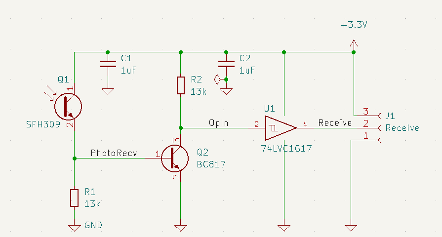
and here is the schematic of the write part:
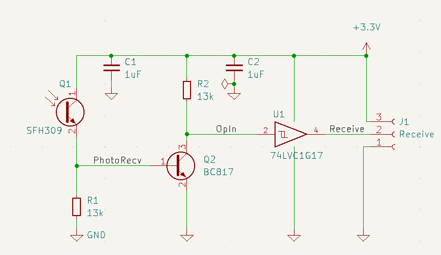
The PCB
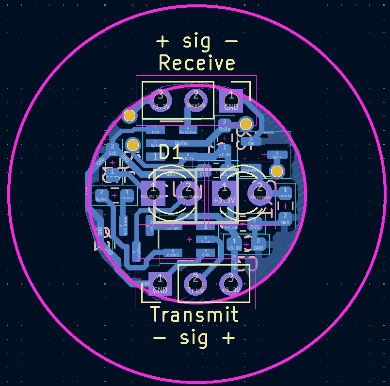
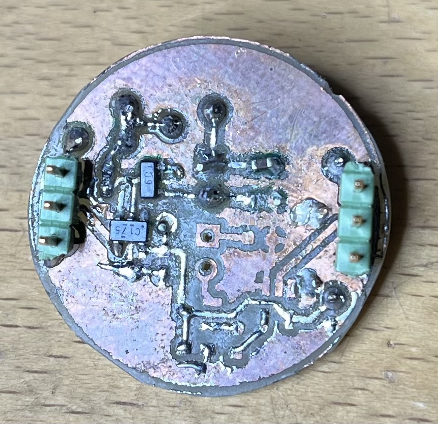
As you can see, I put two connectors on the PCB. One is handling the receive signals, the other is handling the transmit signals. I did this to increase the stability of the connection to the ESP PCB.
Test
I powered the PCB with my lab power supply and connected the receive pin to my oscilloscope. the signal shown below is the power button I pressed on my TV remote control.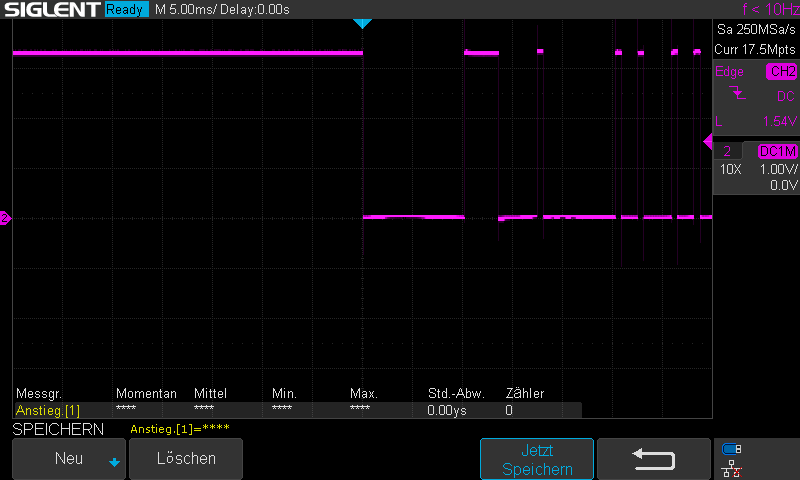
The final PCB
Here is the final result. During development I found out that I do not need the transmission capability as the ISKRA MT 175 send all relevant values cyclicly once it is unlocked.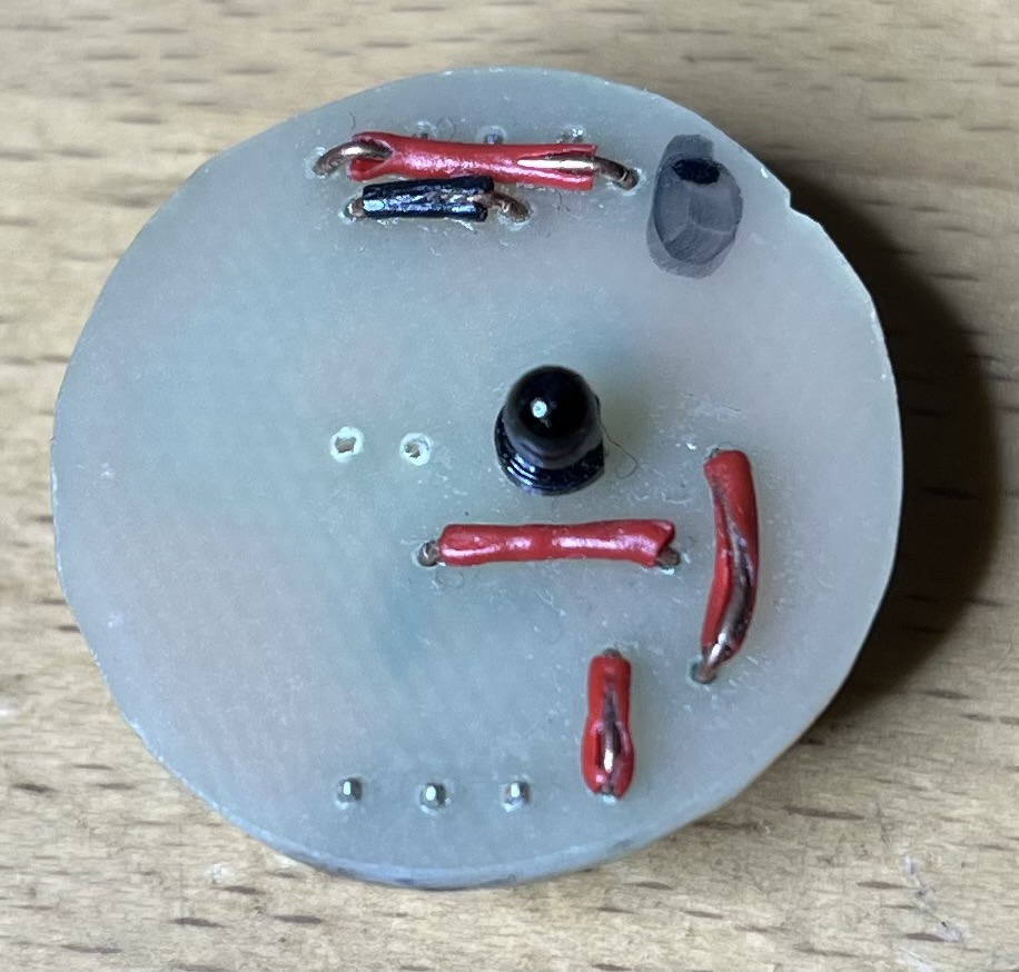
Last edit: 2026-10-17
